Calculation of Punch and Die Cutting Edge Dimensions
Calculation of Punch and Die Cutting Edge Dimensions
 The dimensional accuracy of stamped parts is directly influenced by the cutting edge dimensions and tolerances of punches and dies. Proper clearance values are maintained through precise control of these dimensions and tolerances. Their determination requires consideration of multiple factors including shearing deformation characteristics, part precision requirements, tool wear patterns, and manufacturing constraints.
Fundamental Principles for Cutting Edge Dimension Calculation
Extensive practice demonstrates that:
- Blanked part dimensions closely correspond to die edge dimensions
- Punched hole dimensions align with punch edge dimensions
In measurement and application: - Blanked parts are referenced by their maximum material condition (larger end dimensions)
- Punched holes are referenced by their minimum material condition (smaller end dimensions)
Both are based on the shear band dimensions.
Tool wear characteristics:
- Punches gradually wear smaller during operation
- Dies progressively wear larger
Based on these observations, the following design principles apply:
- Reference Selection:
- For blanking: Part dimensions are die-dependent → Die serves as reference, clearance applied to punch
- For punching: Hole dimensions are punch-dependent → Punch serves as reference, clearance applied to die
Note: As tool wear occurs during production, punch-die clearance increases. Therefore, designs should incorporate the minimum allowable clearance.
- Wear Compensation:
- Blanking dies: Nominal die size should equal the lower limit of part tolerance
- Punching dies: Nominal punch size should equal the upper limit of hole tolerance
This ensures continued production of in-spec parts throughout the tool’s service life.
- Manufacturing Tolerances (δp for punch, δd for die):
- Typically 2-3 precision grades tighter than part requirements
- For non-toleranced parts:
- Non-circular features: IT14 per GB/T “Non-Fit Dimensional Tolerances”
- Circular features: IT10
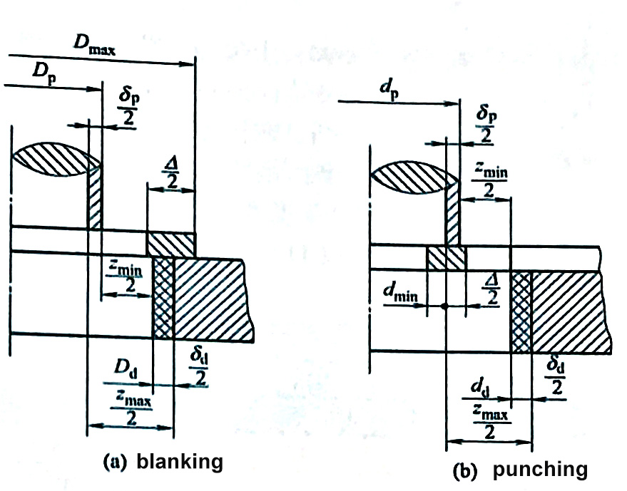
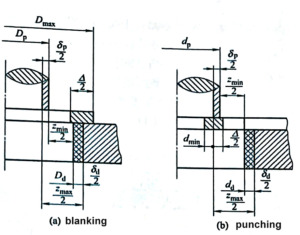
- Tolerance Notation Standards:
- Die edges: Positive deviation (+Δ)
- Punch edges: Negative deviation (-Δ)
- Center distances and non-wearing dimensions: Bilateral deviation (±Δ)
(Refer to following Figure for tolerance zone relationships)
Calculation Methods for Cutting Edge Dimensions
Two distinct approaches exist based on manufacturing and measurement techniques:
1. Separate Punch and Die Machining
For simple geometries (round/square shapes)
Clearance control requirement:
|δp| + |δd| ≤ Zmax – Zmin
Tolerance determination options:
a) Standard values from Table 4-15
b) For regular shapes:
- Punch: IT6 grade
- Die: IT7 grade (per GB/T 1800.4-2009)
c) Calculated values: - δp = 0.4(Zmax – Zmin)
- δd = 0.6(Zmax – Zmin)
2. Matched Tooling Approach
For complex geometries or thin materials
Methodology:
- Designate one component (punch or die) as master
- Machine counterpart to match with specified clearance
- Only master component carries full dimensional tolerances
- Matched component specifies nominal size + clearance
Advantages:
- Eliminates tolerance stack-up constraints
- Typical tolerance: δ = Δ/4 (Δ = part tolerance)
- Reduces manufacturing complexity
- Lowers production costs
- Maintains tight clearance control
Implementation Guidelines:
Blanking Dies:
- Master: Die
- Matched: Punch
- Drawing note: “Punch to match actual die dimensions with bilateral clearance Zmin”
Punching Dies:
- Master: Punch
- Matched: Die
- Punch wear categories: Size may increase, decrease, or remain stable
- Drawing note: “Die to match actual punch dimensions with bilateral clearance Zmin”
Company Profile
We are a precision metal stamping specialist headquartered in Ningbo, China, offering:
- Custom metal stamping and deep-drawn components
- Complete tooling solutions
- Engineering design support
- Cost-optimized manufacturing
- Consistent quality assurance
For partnership opportunities or technical inquiries, please contact our engineering team.
